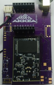
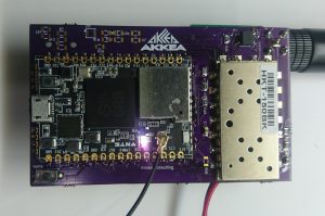
 So I finally have a design of the TNC I’ve been working on that I think is ready for release. Initially this started with me wanting a replacement for my mobilinkd and AP510. With feature creep it has turned into much more.
The current board has a VHF radio module, a CHIP Pro computer module running Linux ( NTC calls it gadget OS ) and a Mikrobus slot. I’m currently using the Mikrobus for a GPS module but there are lots of variants.
Features
I’m going to split the features into ones I’ve had the time to test with the current design and features that did work on previous designs but haven’t been tested on the current design or haven’t been tried at all.
Current features
- The OS is a slightly modified Gadget OS
- There is a web server that can display maps, receive APRS beacons and send APRS messages ( receive was broken last time I checked )
- Send and receive APRS messages using direwolf
- APRX interface for viscous digipeating
- Mikrobus slot that supports 3.3V serial modules for GPS
- 1W VHF module
Previously working features
- WiFi access point
- mobilnkd type interface for connecting to HT radios for higher power TX – I used the same interface as the mobilinkd so their cable will work
- messaged.py module for sending and receiving APRS messages
Untested HW features
- UHF radio module
- IO output including solid sate relays capable of switching 12V 1.5A DC
- SD card
- 2nd USB port
Possible Additional Software Features
- Cross band audio repeater
- Cross band digipeater
- BT/WiFi to APRS/AX25 modem
Design Files
I’ve decided to open source all of the design including the hardware and software.
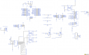
 You can view the schematic and layout at upverter.
There are a few different software repositories
The CHIP Pro gadget OS is on github.
There is a repository that contains the gadget OS configuration files and install scripts for the webserver environment on gitlab.
Getting and Building the Design
The PCBs can be ordered from OSH Park
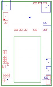
Here is the assembly drawing
The full BOM is available from upverter but for the currently working features there is a much smaller subset.
Current BOM
- CHIP Pro CPU board
- 1W VHF radio
- R30 10K 0805
- R41 R42 1.1K 0805
- R32 R33 R37 2K 0805
- C3 C8 100nF 0805
- Solid state relay
- Mikrobus header
- Battery connector
- SMA antenna connector
Here is a digikey version of the BOM.The total BOM cost including the PCB but excluding the antenna is around $60.
Assembling the Boards
Some of the parts are small ( 0805 ) so you will need soldering gear that can do finer parts. All of the fine parts get mounted on the top side of the board near the RF module. The connectors all go on the back of the board.
Next Steps
 The software needs some polishing so if anyone wants to contribute patches please do.
It also needs a case designed for it so I’ll likely start doing that in openscad soon.
Since I’ve started this design NTC has become less and less responsive so I don’t know is there’s any future in the CHIP or CHIP Pro boards. I hope there is but I’ve been waiting for a year fro the CHIP pro’s I ordered and it’s been more than 4 months since I received any email from them. If anyone else has actually got an email from them I’d be interested in hearing about it.
Thanks goes out to Herb Peyerl andRob Riggs for design assistance and motivation during the project.
BTW there is also an original NTC CHIP design.


First of all, thank you so much for offering this as open source. It’s projects like these that make me proud to be part of the amateur radio community.
It looks like a very fun, and achievable project.
73 de w8tam