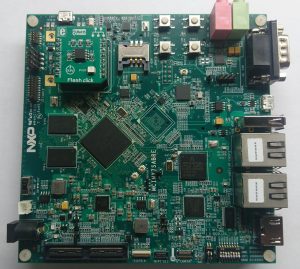
I’ve been working with the Freescale i.MX7 Sabre board and I wanted to free up the SD card so I could do some SDIO testing. I decided to boot the board from SPI flash ( I needed to test that out anyway ) and then load a kernel and rootfs across the network.
On the i.MX7 board there is a mikroBUS connector which basically just breaks out SPI/I2C/serial and a couple of GPIOs. There is a 8Mb SPI flash that you can get for this bus called the flash click. Just what I needed so I ordered one.
The documentation the board comes with claims the flash chip is a M25P80, no problem u-boot supports that. I added the config below into “include/configs/mx7dsabresd.h” to enable the u-boot SPI flash tools.
#define CONFIG_CMD_SF
#define CONFIG_MXC_SPI
Also enable SPI flash in the defconfig “configs/mx7dsabresd_secure_defconfig”
CONFIG_SPI_FLASH=y
You also need to add some code to your machine initialisation “board/freescale/mx7dsabresd/mx7dsabresd.c” so that the pads get configured properly.
define SPI_PAD_CTRL \
  (PAD_CTL_HYS | PAD_CTL_DSE_3P3V_49OHM | PAD_CTL_SRE_FAST)

static iomux_v3_cfg_t const ecspi3_pads[] = {
  MX7D_PAD_SAI2_RX_DATA__ECSPI3_SCLK | MUX_PAD_CTRL(SPI_PAD_CTRL),
  MX7D_PAD_SAI2_TX_SYNC__ECSPI3_MISO | MUX_PAD_CTRL(SPI_PAD_CTRL),
  MX7D_PAD_SAI2_TX_BCLK__ECSPI3_MOSI | MUX_PAD_CTRL(SPI_PAD_CTRL),
  MX7D_PAD_SAI2_TX_DATA__GPIO6_IO22 | MUX_PAD_CTRL(NO_PAD_CTRL),
};

int board_spi_cs_gpio(unsigned bus, unsigned cs)
{
       return (bus == 2 && cs == 0) ? (IMX_GPIO_NR(6, 22)) : -1;
}

static void setup_spi(void)
{
       imx_iomux_v3_setup_multiple_pads(ecspi3_pads, ARRAY_SIZE(ecspi3_pads));
}
One more edit to “board/freescale/mx7dsabresd/mx7dsabresd.c” to get the code above called. Into the function board_init add this
#ifdef CONFIG_MXC_SPI
       setup_spi();
#endif
So then I built myself a new u-boot
make mx7dsabresd_secure_defconfig
CROSS_COMPILE=arm-linux-gnueabihf- make
Now take your newly minted u-boot, burn it to an SD card.
sudo dd if=u-boot.imx of=/dev/mmcblk0 seek=1 bs=1024
and it boots the board
U-Boot 2016.11-rc3-00044-g38cacda-dirty (Nov 09 2016 - 15:59:35 -0700)

CPU:   Freescale i.MX7D rev1.1 996 MHz (running at 792 MHz)
CPU:   Commercial temperature grade (0C to 95C) at 35C
Reset cause: POR
Board: i.MX7D SABRESD in secure mode
I2C:   ready
DRAM:  1 GiB
PMIC: PFUZE3000 DEV_ID=0x30 REV_ID=0x11
MMC:   FSL_SDHC: 0, FSL_SDHC: 1
Video: 480x272x24
In:    serial
Out:   serial
Err:   serial
switch to partitions #0, OK
mmc0 is current device
Net:   FEC0
Hit any key to stop autoboot:  0
=>
Excellent now I want to scan for the flash chip so that I can burn my new u-boot to it.
=> sf probe 2:0
SF: Unsupported flash IDs: manuf 1c, jedec 3014, ext_jedec 1c30
Failed to initialize SPI flash at 2:0
WTF that’s not the jedec id for a N25P80. So if you go back to the link near the top of the page the mikroBUS flash click actually uses the EN25Q80B which is not in mainline u-boot. Back to the code we go.
Edit “drivers/mtd/spi/sf_params.c” and right after “#ifdef CONFIG_SPI_FLASH_EON /* EON */” add the line below.
{"EN25Q80B", 0x1c3014, 0x0, 64 * 1024, 16, 0},
You’ll also nee to edit your config again “include/configs/mx7dsabresd.h” and add EON SPI to the configuration.
#define CONFIG_SPI_FLASH_EON
Rebuild it and burn it back to the SD card and try the probe again.
=> sf probe 2:0
SF: Detected EN25Q80B with page size 256 Bytes, erase size 64 KiB, total 1 MiB
So now u-boot can understand the flash, lets erase enough space for u-boot it and flash it.
=> sf erase 0 80000
SF: 524288 bytes @ 0x0 Erased: OK
=> mmc read 0x80000000 2 400

MMC read: dev # 0, block # 2, count 1024 ... 1024 blocks read: OK
=> sf write 0x80000000 400 80000
device 0 offset 0x400, size 0x80000
SF: 524288 bytes @ 0x400 Written: OK
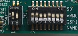
Now set the jumpers to boot from the SPI flash, remove the SD card and reset the board.
Here’s the mikroBUS flash click patch that should apply to mainline u-boot.

Hello Angus,
Your post is very helpful and is the only source of information about mikroBus 🙂
So, I want to understand your configuration for SW2 switch:
11001000 – this sequence is absent in mx7d sabre board documentation, it has only following:
001… – SD/eSD
010… – MMC/eMMC
011… – NAND Boot
100… – QSPI
I think QSPI should be used? Am I correct?
And the second question. I made all needed changes in uboot for my NAND chip (w25n01gv). I was able to repeat your lesson about sf commands:
“sf probe 2:0 20000000 “# I specified SPI frequency to 20Mhz, without this I was not able to work with a chip
“sf erase …”
“sf read …”
“sf write …”
I was able to write data from memory to flash, and read it back to proof that it was written. (I was filling memory region with FF before reading the flash)
Seems it works. But after board restart, flash was not contain expected data.
Not sure where I should dig, may be you can give me a tip?
So it’s been a long time since I worked with this and I no longer have access to the board but from my hazy recollection.
I think that SW3 is supposed to be prefix onto SW2 to get the boot mode so that should be 1011001000 for the boot mode and IIRC the 3rd bit from the right was either don’t care or specified CS1 instead of CS0.
I also had problems if I didn’t specify a bus speed.
A couple of questions to clear up your comment.
1) Does the board reboot using the flash you wrote or some other boot device.
2) It doesn’t read back even after setting the bus speed correctly ( I think I used 10 Mhz )
SW 3 specifying boot mode:
00 – Internal fuses
01 – Mfg link / Serial downloader
10 – Internal boot
11 – test mode.
So, ok for now 🙂 I just can try different variants.
According clearing up questions:
1) The board is mx7 sabresd, I am buuting from SD card into U-Boot shell
2) So I can not use any speed in some valid range specified by datasheet? Ok will try 10 Mhz as well.
But it is so strange to see correct values from flash before rebooting and no values after rebooting. Is there some cache for “sf read/write” commands?
Right SW3 on internal boot and there is some fall back mechanism so I think the boot order ended up being Mikro bus flash if it could find it and SD card if that wasn’t present.
The flash was very picky about what speeds it work correctly. From memory speeds approaching 50 Mhz would identify the chip correctly and look like they wrote but would fail a verify and the same for speeds under 5 Mhz .