Socat, sslh and stunnel to share https port 443

The instructions below assume you are using Ubuntu 16.04 but they will work for other Linuxes with minor modifications. The instructions below will also conflict with a webserver listening on port 443 ( https ) so you’ll need to disable it. Once the setup below is complete your https connections will get seamlessly forwarded to port 80.

Setup letsencrypt keys

For the SSL connection to be secure and trusted by browsers and other software you need to have a certificate signed by a recognised certificate authority. The easiest way to do this is to use letsencypt’s certbot. I’m not going to go into how to get the certificate as there are too many ways depending on your configuration. Just follow letsencrypt’s documentation to generate a key for your "servernname.com" that will get used in the rest of these instructions.

You could also use a self signed key but that may cause you problems with stateful firewalls.

Setup stunnel

With your certificate installed on the server you can now setup stunnel to use it. crow shows a partial setup here. I think he’s limited the ciphers for increased security but I found it was not necessary.

Install stunnel4

sudo apt-get install stunnel4

So the setup in /etc/stunnel/stunnel.conf I am using looks like this

pid = /var/run/stunnel.pid
cert = /etc/letsencrypt/live/servername.com/fullchain.pem
key = /etc/letsencrypt/live/servername.com/privkey.pem
[ssh]
accept = servername.com:443
connect = localhost:80

You also need to enable stunnel in /etc/default/stunnel4.conf by setting ENABLED=1

restart stunnel to use the new configuration.

systemctl restart stunnel4

At this point you can test the stunnel setup by going to “http://servername.com” with your browser and you will have a secure connection to your http server.

To prep for the sslh configuration change

connect = localhost:80

in /etc/stunnel/stunnel.conf to

connect = localhost:1022

and then restart stunnel again.

Setup sslh

sslh will redirect the sessions decrypted by stunnel to the correct port on your server.

You need to install sslh

sudo apt-get install sslh

The minimum services I wanted are ssh and http so my configuration in /etc/default/sslh looks like this.

RUN=yes

# binary to use: forked (sslh) or single-thread (sslh-select) version
DAEMON=/usr/sbin/sslh

DAEMON_OPTS="--user sslh --listen 127.0.0.1:1022 --http 127.0.0.1:80 --ssh 127.0.0.1:22 --pidfile /var/run/sslh/sslh.pid"

The sslh documentation says that OpenVPN, tinc, XMPP are also supported but I didn’t need those so my configuration doesn’t support them. You can now restart sslh

sudo systemctl restart sslh

This would be another good time to test the stunnel -> sslh -> httpd redirection by visiting “http://servername.com” in your browser.

Client side ssh setup

Once all of the above is complete and assuming that you have an ssh server that you can connect to on port 22 of your server the ssh client can be setup to use the ssl tunnel. The ssh session needs to wrapped in the ssl session to be able to connect to the server so I used the ssh ProxyCommand to accomplish this. Add the section below to your ~/.ssh/config on your client machine

Host servername.com
ProxyCommand /usr/bin/socat - OPENSSL:servername.com:443

From the client you should now be able to connect to your server by doing

ssh servername.com

If you get errors from ProxyCommand about your keys or if you used a self signed certificate you will need to turn off key verification.

Host servername.com
ProxyCommand /usr/bin/socat - OPENSSL:servername.com:443,verify=0

There is usually one other modification I have in my ssh config and that is a DynamicProxy so that stateful packet inspection doesn’t interfere. So the final configuration looks like this.

Host servername.com
DynamicForward localhost:2121
ProxyCommand /usr/bin/socat - OPENSSL:servername.com:443

The interested reader should look into FoxyProxy to see how this might be used.

Using letsencrypt with stunnel

I wanted to use letsencrypt keys and stunnel to encrypt sessions with a valid server key. Once setup the system needed to look like a regular https website with a valid certificate. I’ll explain why I did this in a later posting.

I’m not going to go into getting the original key from letsencrypt as there are too many ways to do it and letsencrypt’s certbot is already well documented.

These instructions are also specific to Ubuntu 16.04 but could be modified for other Linux’s. The instructions below will also conflict with any webserver listening on port 443 (https).

Setup stunnel

In all of the instructions and scripts below replace <servername> with your hostname. <servername> also needs to match you letsencrypt hostname.

sudo apt-get install stunnel4

Edit /etc/default/stunnel4 and change ENABLED=1

Now create a new stunnel conf file in /etc/stunnel/ with the contents below

pid = /var/run/stunnel.pid
cert = /etc/stunnel/stunnel.pem
[ssh]
accept = <servername>:443
connect = 127.0.0.1:80

If you want to connect to something other than you local webserver change the “connect = 127.0.0.1:80” line above.

Now because stunnel needs the fullchain.pem and the privkey.pem in the same file we need to combine the letsencrypt files. Here’s a script ( combine_certs.sh ) that will check the md5sums of the letsencrypt file and generate a new stunnel.pem whenever the originals change.

#!/bin/bash
#
# Copyright (c) 2017 Angus Ainslie 
#

IN_PATH="/etc/letsencrypt/live"
CERT_NAME=$1
OUT_PATH=$2
PEM_NAME=$3

CHAIN_SUM=`md5sum ${IN_PATH}/${CERT_NAME}/fullchain.pem`
KEY_SUM=`md5sum ${IN_PATH}/${CERT_NAME}/privkey.pem`

echo "Chain sum ${CHAIN_SUM}"
echo "Key sum ${KEY_SUM}"

if [ ! -e ${OUT_PATH}/sums ]; then
  echo ${CHAIN_SUM} > ${OUT_PATH}/sums
  echo ${KEY_SUM} >> ${OUT_PATH}/sums
fi

md5sum --status -c ${OUT_PATH}/sums

if [ $? -eq 0 ]; then
  echo "Keys match"
else
  echo "Keys don't match. re-creating pem file"
  cat ${IN_PATH}/${CERT_NAME}/fullchain.pem ${IN_PATH}/${CERT_NAME}/privkey.pem > ${OUT_PATH}/${PEM_NAME}
  echo ${CHAIN_SUM} > ${OUT_PATH}/sums
  echo ${KEY_SUM} >> ${OUT_PATH}/sums
fi

To generate the stunnel.pem file run combine_certs.sh like this

sudo combine_certs.sh <servername> /etc/stunnel stunnel.pem

Because the letsencrypt certificates are short lived their install process adds a cron job that will renew any keys expiring in 30 days or less. So we need to rerun the combine script to keep our stunnel.pem current. Put this crontab in /etc/cron.d

# Copyright (c) 2017 Angus Ainslie <angus at akkea.ca>
#
SHELL=/bin/bash
PATH=/usr/local/sbin:/usr/local/bin:/sbin:/bin:/usr/sbin:/usr/bin

5 */12 * * * root test -x /usr/local/bin/combine_certs.sh && combine_certs.sh  /etc/stunnel stunnel.pem

Now restart stunnel

systemctl restart stunnel4

You will now have a fully functional stunnel listener that will function as an https server.

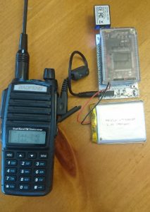
CHIP TNC


I’ve had a mobilinkd for a couple of years now and I like the small form factor and the mobility of the device. I’ve always wanted it to have some additional features such as a connected mode ( either USB or serial ) and the ability to track without the need for a cell phone. Wifi would also be a preferred wireless interface.

I tried using the AP510 to fill some of these features but it’s under powered and prone to burning out it’s LDO.

At the urging of a friend, Herb, I sat down and designed one that fit our needs.

The hardware feature set we decided on

  • Arm SOC module running Linux for TNC
  • Audio/PTT interface for Yaesu and Kenwood/BaoFeng
  • 1W RF module ( could be VHF or UHF )
  • GPS expansion port
  • XBee header

For the ARM module we chose the C.H.I.P. by Next Thing Co. I has a nice small form factor and the site claims you can order 1 – 1 million with very little lead time ( it turns out they are limiting you to 5 at a time right now ). A couple of other nice features of the module are WiFi, bluetooth, Lipo charger and 2 USB ports.

I used the same audio/PTT interface as the mobilinkd so I could reuse the audio cables.

We chose the SR FRS 1W for the on board RF interface. It’s got a nice small form factor but there are some issues with it’s PTT that we are still debugging.

The GPS expansion port is just a slot in the board with serial RX/TX, i2c, 3V3, 5V and GND. I’ve looked at a few GPS modules but haven’t started designing anything yet. Part of the reason I’m holding off is that the side of the board I wanted to put the expansion on would interfere with the USB ports from the CHIP. Until I design a GPS interface module I’m just using a small ND-105 MicroUSB adapter.

I chose the XBee header because there are a number of boards that are already designed for that form factor that support a large number of RF protocols. Now, because of the issues with the GPS expansion slot I might just design a GPS module to plug in there.

Running the audio interface and the GPS dongle from a 2500mAH battery the board can run for about 4 hours. I need to do some optimisation to try and get that into the 8 hours range.


Software features

  • Debian – standard CHIP install
  • Direwolf – so the device can function as a TNC/digipeater/X25 modem
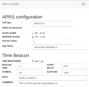
  • Lighttpd webserver for configuration and UI
  • Host AP and wifi client simultaneously
  • APRX for viscous digipeating

I had to make some modifications to Direwolf to get it to handle multiple TCPIP clients, as APRX, the web ui and a message daemon all share Direwolf.

The UI is written in python using the web.py framework and currently supports these features.

  • List of recent APRS beacons
  • Settings for APRX, Direwolf and PTT
  • Send and receive APRS messages
  • Maps for to show beacon locations
  • Display Direwolf logs for debugging

These all need cleaning up but for the most part are functional.

For the message interface a message daemon is needed to store messages for the interface and handle message ACKs. It attempts to re-transmit the message 3 times or until it is properly ACKed. The UI can also re-send failed messages.

I want to add a feature that failed messages will be re-transmitted when the messaged receives a beacon from the intended recipient.

Moving forward

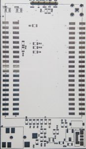
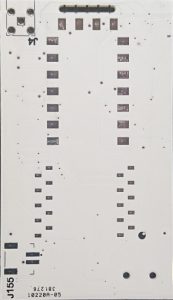
The boards arrived a week ago and apart from a few minor difficulties ( wrong parts, reversed RF module foot prints , you know the usual ) are working working well. So a second rev will be required. But a new rev means new features , right ?


REV2 features

  • Concurrent RF module and audio interface. The unit could be across band digipeater or repeater
  • LED TX/RX indicator
  • Squelch tied to an interrupt for low power modes
  • CHIPProadapter to mitigate CHIP supply issues

The code is all hosted on gitlab right now in a private repo but I’ll probably open that up if there are any others interested in helping out.

Booting the i.MX7 Sabre board from the mikroBUS SPI flash

dsc_0199
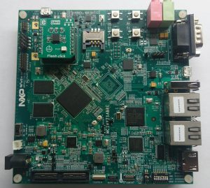
I’ve been working with the Freescale i.MX7 Sabre board and I wanted to free up the SD card so I could do some SDIO testing. I decided to boot the board from SPI flash ( I needed to test that out anyway ) and then load a kernel and rootfs across the network.

On the i.MX7 board there is a mikroBUS connector which basically just breaks out SPI/I2C/serial and a couple of GPIOs. There is a 8Mb SPI flash that you can get for this bus called the flash click. Just what I needed so I ordered one.

The documentation the board comes with claims the flash chip is a M25P80, no problem u-boot supports that. I added the config below into “include/configs/mx7dsabresd.h” to enable the u-boot SPI flash tools.

#define CONFIG_CMD_SF
#define CONFIG_MXC_SPI

Also enable SPI flash in the defconfig “configs/mx7dsabresd_secure_defconfig”

CONFIG_SPI_FLASH=y

You also need to add some code to your machine initialisation “board/freescale/mx7dsabresd/mx7dsabresd.c” so that the pads get configured properly.

define SPI_PAD_CTRL \
  (PAD_CTL_HYS | PAD_CTL_DSE_3P3V_49OHM | PAD_CTL_SRE_FAST)

static iomux_v3_cfg_t const ecspi3_pads[] = {
  MX7D_PAD_SAI2_RX_DATA__ECSPI3_SCLK | MUX_PAD_CTRL(SPI_PAD_CTRL),
  MX7D_PAD_SAI2_TX_SYNC__ECSPI3_MISO | MUX_PAD_CTRL(SPI_PAD_CTRL),
  MX7D_PAD_SAI2_TX_BCLK__ECSPI3_MOSI | MUX_PAD_CTRL(SPI_PAD_CTRL),
  MX7D_PAD_SAI2_TX_DATA__GPIO6_IO22 | MUX_PAD_CTRL(NO_PAD_CTRL),
};

int board_spi_cs_gpio(unsigned bus, unsigned cs)
{
       return (bus == 2 && cs == 0) ? (IMX_GPIO_NR(6, 22)) : -1;
}

static void setup_spi(void)
{
       imx_iomux_v3_setup_multiple_pads(ecspi3_pads, ARRAY_SIZE(ecspi3_pads));
}

One more edit to “board/freescale/mx7dsabresd/mx7dsabresd.c” to get the code above called. Into the function board_init add this

#ifdef CONFIG_MXC_SPI
       setup_spi();
#endif

So then I built myself a new u-boot

make mx7dsabresd_secure_defconfig         
CROSS_COMPILE=arm-linux-gnueabihf- make

Now take your newly minted u-boot, burn it to an SD card.

sudo dd if=u-boot.imx of=/dev/mmcblk0 seek=1 bs=1024

and it boots the board

U-Boot 2016.11-rc3-00044-g38cacda-dirty (Nov 09 2016 - 15:59:35 -0700)

CPU:   Freescale i.MX7D rev1.1 996 MHz (running at 792 MHz)
CPU:   Commercial temperature grade (0C to 95C) at 35C
Reset cause: POR
Board: i.MX7D SABRESD in secure mode
I2C:   ready
DRAM:  1 GiB
PMIC: PFUZE3000 DEV_ID=0x30 REV_ID=0x11
MMC:   FSL_SDHC: 0, FSL_SDHC: 1
Video: 480x272x24
In:    serial
Out:   serial
Err:   serial
switch to partitions #0, OK
mmc0 is current device
Net:   FEC0
Hit any key to stop autoboot:  0 
=>

Excellent now I want to scan for the flash chip so that I can burn my new u-boot to it.

=> sf probe 2:0
SF: Unsupported flash IDs: manuf 1c, jedec 3014, ext_jedec 1c30
Failed to initialize SPI flash at 2:0

WTF that’s not the jedec id for a N25P80. So if you go back to the link near the top of the page the mikroBUS flash click actually uses the EN25Q80B which is not in mainline u-boot. Back to the code we go.

Edit “drivers/mtd/spi/sf_params.c” and right after “#ifdef CONFIG_SPI_FLASH_EON /* EON */” add the line below.

  {"EN25Q80B",        0x1c3014, 0x0, 64 * 1024,  16, 0},

You’ll also nee to edit your config again “include/configs/mx7dsabresd.h” and add EON SPI to the configuration.

#define CONFIG_SPI_FLASH_EON

Rebuild it and burn it back to the SD card and try the probe again.

=> sf probe 2:0
SF: Detected EN25Q80B with page size 256 Bytes, erase size 64 KiB, total 1 MiB

So now u-boot can understand the flash, lets erase enough space for u-boot it and flash it.

=> sf erase 0 80000 
SF: 524288 bytes @ 0x0 Erased: OK
=> mmc read 0x80000000 2 400

MMC read: dev # 0, block # 2, count 1024 ... 1024 blocks read: OK
=> sf write 0x80000000 400 80000
device 0 offset 0x400, size 0x80000
SF: 524288 bytes @ 0x400 Written: OK

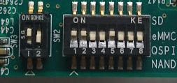
Now set the jumpers to boot from the SPI flash, remove the SD card and reset the board.dsc_0201

Here’s the mikroBUS flash click patch that should apply to mainline u-boot.

Scaling an STL in FreeCAD

I found a new way to scale STLs in FreeCAD where you don’t need to use the Python console.

Import the STL.
Go to the Part Workbench.
Select the STL in the Model list
Menu: Part->Create shape from mesh…
Select the new part
Menu: Part->convert to solid
Select the new part
Menu: Part->Refine shape
Change to the Draft Workbench
Menu: Draft->Clone

Now you can adjust the scale in the properties window of the clone.

Scaling Upverter STL Output in FreeCAD

Upverter has a nice STL export ( when it works ) of your board so you can do mechanical modelling for your design. Unfortunately when it gets imported into FreeCAD the scale is 10 times too small.

FreeCAD as of 0.15 does not have menu item that allows you to scale mesh imports. Luckily the python console can do the scaling of imported meshes.

First import the mesh ( STL file ) that you want to add to the current design. Select it in the “Combo view->Model” tree on the left of the FreeCAD screen. Then use the python console ( View->Views->Python console ) with the code below to scale it up 10 times.

import Mesh,BuildRegularGeoms
mat=FreeCAD.Matrix()
mat.scale(10.0,10.0,10.0)
mesh=App.ActiveDocument.ActiveObject.Mesh.copy()
mesh.transform(mat)
Mesh.show(mesh)

Now you should have a correctly sized copy of the STL board that you imported.

Here is the original post on importing and scaling ( I wanted to scale a mesh I had already imported ).

Aerogarden Bulb Mod

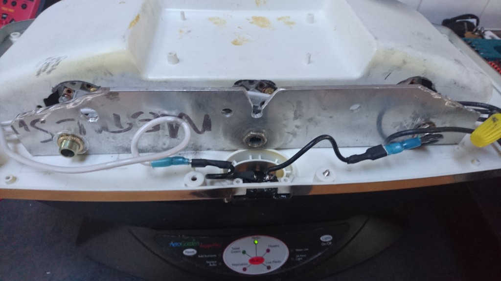
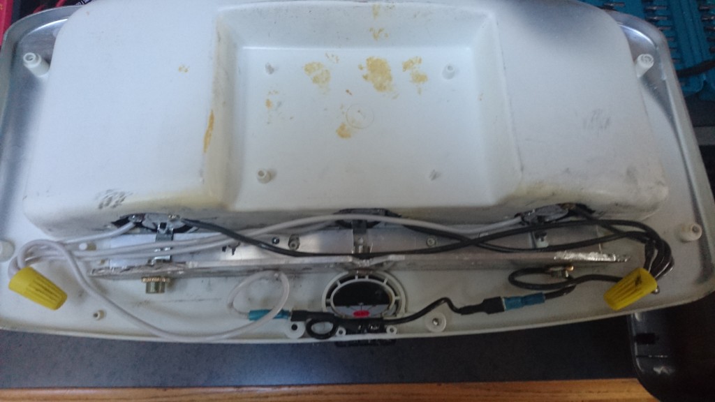
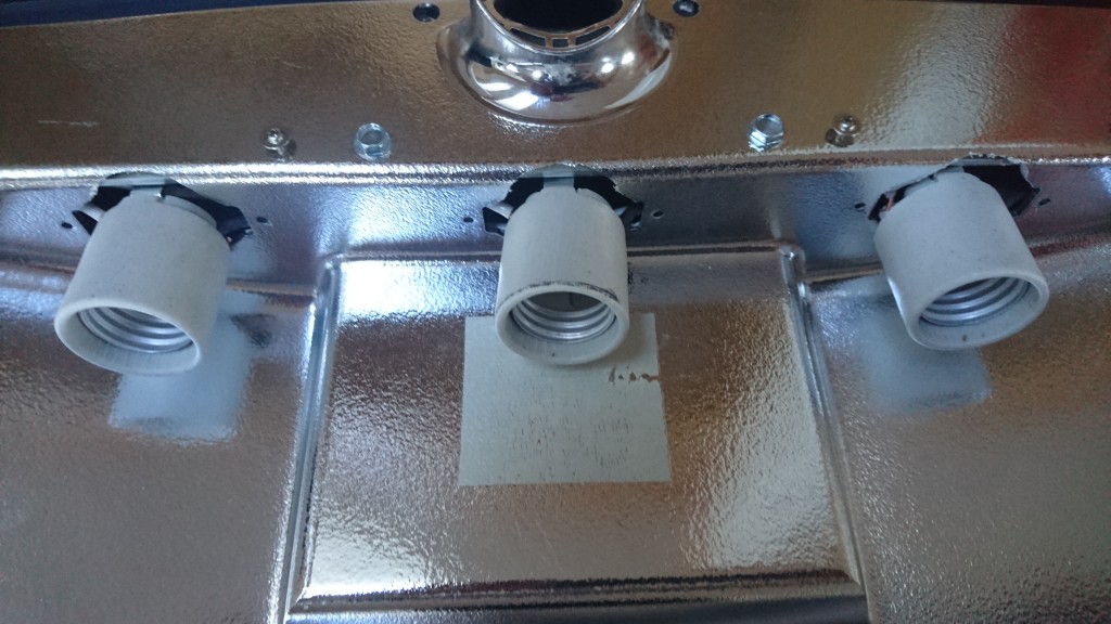
DSC_0220I’ve had this Aerogarden for a while but most of it’s life has been spent in a box in the garage because the lights quit working shortly after the 1 year warranty ran out. I decided to take it out this weekend and figure out what the issue was.

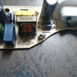
DSC_0217I disassembled the the light fixture and pulled out the power board and there are 2 250V 3A fuses on there. Both of then were blown. I de-soldered those thinking I would just replace them and the board would work. Then I got to thinking why do I want to fix the power supply for the proprietary ( and not very long lasting ) bulbs so instead I hacked it to take A19 ( “standard” ) light bulbs.

I didn’t take pictures along the way but the hack is pretty simple.

  1. Disassemble the light fixture – 2 of the bolts are Torx. You don’t need to remove the 2 screws next to the power plug
  2. Remove the old power supply and CFL mounting brackets
  3. Mark the size of the holes for the new light fixtures – medium socket
  4. Cut out the holes with a Dremel. I left the original CFL mounting holes in case I wanted to go back to the old bulbs.
  5. Cut a piece of aluminium L bracket to length and height. Notice there is a notch part way though the light fixture that you need to make room for. I also added 4 holes for alignment to the old screw mounts. I would check to make sure that the fixture has room to close properly at this point.
  6. Attach some 14 gauge wire to the bases and mount them to the L bracket.
  7. Attach the new wire to the power plug on the fixture.
  8. Slide the bases through the holes from step 3.
  9. Mount the L bracket to the fixture with 2 Tek self taping bolts.
  10. Re-assemble the fixture and you’re all done.

DSC_0214

DSC_0215
DSC_0213

I’ve currently got 3 60W incandescent grow bulbs in there but I’m on the lookout for some LED or CFL grow lights.

SWD with the MDBT40 BLE module

IMG_20150301_173929

I was recently introduced to the MDBT40 module that is based on the Nordic nRF51822. The processor nicely solves a number problems I’ve been looking at and the fact that it’s Bluetooth Smart also solves how I’ll get the data from it.

I designed some custom hardware ( the picture at left ) around the module and I needed some way to program it. My earlier post shows my investigations with SWD and OpenOCD.I put a SWD header on the board to re-program it.

OpenOCD Configuration for the nRF51822

bishop on the Nordic Developer Zone figured out how to get the nRF51822 part working with S-Link and OpenOCD. I took his configuration and adjusted it to work with the bus blaster v3.

source [find  interface/ftdi/dp_busblaster_kt-link.cfg]
transport select swd
set WORKAREASIZE 0
source [find target/nrf51.cfg]

Save it as nrf51822.cfg so then you can start openocd with it.

$ openocd -f target/nrf51822.cfg

OpenOCD defaults to a telnet interace on 4444.

$ telnet 127.0.0.1 4444
Trying 127.0.0.1...
Connected to 127.0.0.1.
Escape character is '^]'.
Open On-Chip Debugger
> halt                                    
target state: halted
target halted due to debug-request, current mode: Thread
xPSR: 0x21000000 pc: 0x000163da msp: 0x20003fd8
> nrf51 mass_erase                        
> flash write_image _build/akkea1_tfw.hex
Padding image section 0 with 2112 bytes
Padding image section 1 with 3572 bytes
Padding image section 2 with 1 bytes
not enough working area available(requested 32)
no working area available, falling back to slow memory writes
wrote 95556 bytes from file _build/akkea1_tfw.hex in 14.267832s (6.540 KiB/s)
> reset

The board is now prgrammed with your custom firmware. This should work with any MDBT40 based board the has the 12K programming resistor per the Raytac application note. It should also work with other nRF51822 based board with a SWD interface

Recovering a bricked CC3D board using a bus blaster

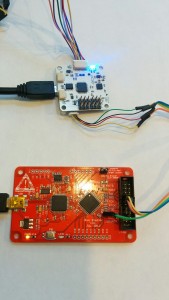
IMG_20150214_155435A few months ago I went to upgrade my OpenPilot CC3D board an something went amiss and I ended up trashing the bootloader. I didn’t have a SWD dongle to reprogram it with so its been collecting dust. I just purchased a v3 bus blaster for a different project I’m working on and it has a SWD firmware so I thought I’d try and recover the CC3D. Below are the steps I used.

Download and install the latest OpenOCD

git clone git://git.code.sf.net/p/openocd/code openocd
cd openocd/
./bootstrap
./configure --prefix=/usr
make
sudo make install

Re-flash the Bus Blaster v3 for KT-link buffer

The instructions below came from here

git clone https://github.com/bharrisau/busblaster.git
cd busblaster/synthesis
openocd -f board/dp_busblaster_v3.cfg -c "adapter_khz 1000; init; svf system.svf; shutdown"

Getting/Building the bootloader

Now you need to get a bootloader to flash into the CC3D. You might be able to download bl_coptercontrol.hex but I’ve already got the OpenPilot development environment installed so I just built it using

make all_bl all_bu

If you don’t have the dev environment setup there are build instructions.

Here is the file I used bl_coptercontrol.hex but the regular disclaimers apply, if this file damages or bricks your CC3D I am not responsible.

OpenOCD config file

You need create a flashing script “cc3d-swd.cfg” to pass to OpenOCD.

source /usr/share/openocd/scripts/interface/ftdi/dp_busblaster_kt-link.cfg
transport select swd
source [find target/stm32f1x.cfg]

proc program_device () {
    reset init
        sleep 50
        flash probe 0
        sleep 50
        flash protect 0 0 last off
        sleep 50
        flash write_image erase unlock "path_to_hex_file/bl_coptercontrol.hex"
        sleep 50
        reset run
}

init
program_device ()
exit

Obiously replace “path_to_hex_file” to where you built or downloaded bl_coptercontrol.hex

Connect the bus blaster to the CC3d

I got the cable connections from here.

     adapter         ┊            target
                     ┊
     GND ──────────────────────── GND
                     ┊
     TCK ──────────────────────── SWCK
                     ┊
     TMS ──────────────────────── SWDAT
                     ┊

Finally reflashing the CC3D bootloader

openocd -f cc3d-swd.cfg

Mini Quadcopter Parts

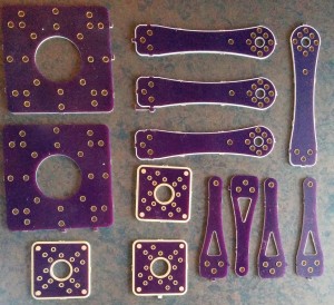
I created some CAD drawings for quadcopter parts I kept breaking. I got tired of making and cutting out the fibreglass myself so I created some Oshpark boards.

You can go here to order your very own Quadcopter parts

Here’s what the first batch looked like. I didn’t like the look of the power board so I did a new layout for my second batch.

I’ve tried the screw positions with the KK multirotor board and the CC3D flight control board.

IMG_20150116_164459