Scaling an STL in FreeCAD

I found a new way to scale STLs in FreeCAD where you don’t need to use the Python console.

Import the STL.
Go to the Part Workbench.
Select the STL in the Model list
Menu: Part->Create shape from mesh…
Select the new part
Menu: Part->convert to solid
Select the new part
Menu: Part->Refine shape
Change to the Draft Workbench
Menu: Draft->Clone

Now you can adjust the scale in the properties window of the clone.

Scaling Upverter STL Output in FreeCAD

Upverter has a nice STL export ( when it works ) of your board so you can do mechanical modelling for your design. Unfortunately when it gets imported into FreeCAD the scale is 10 times too small.

FreeCAD as of 0.15 does not have menu item that allows you to scale mesh imports. Luckily the python console can do the scaling of imported meshes.

First import the mesh ( STL file ) that you want to add to the current design. Select it in the “Combo view->Model” tree on the left of the FreeCAD screen. Then use the python console ( View->Views->Python console ) with the code below to scale it up 10 times.

import Mesh,BuildRegularGeoms
mat=FreeCAD.Matrix()
mat.scale(10.0,10.0,10.0)
mesh=App.ActiveDocument.ActiveObject.Mesh.copy()
mesh.transform(mat)
Mesh.show(mesh)

Now you should have a correctly sized copy of the STL board that you imported.

Here is the original post on importing and scaling ( I wanted to scale a mesh I had already imported ).

Aerogarden Bulb Mod

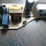
DSC_0220I’ve had this Aerogarden for a while but most of it’s life has been spent in a box in the garage because the lights quit working shortly after the 1 year warranty ran out. I decided to take it out this weekend and figure out what the issue was.

DSC_0217I disassembled the the light fixture and pulled out the power board and there are 2 250V 3A fuses on there. Both of then were blown. I de-soldered those thinking I would just replace them and the board would work. Then I got to thinking why do I want to fix the power supply for the proprietary ( and not very long lasting ) bulbs so instead I hacked it to take A19 ( “standard” ) light bulbs.

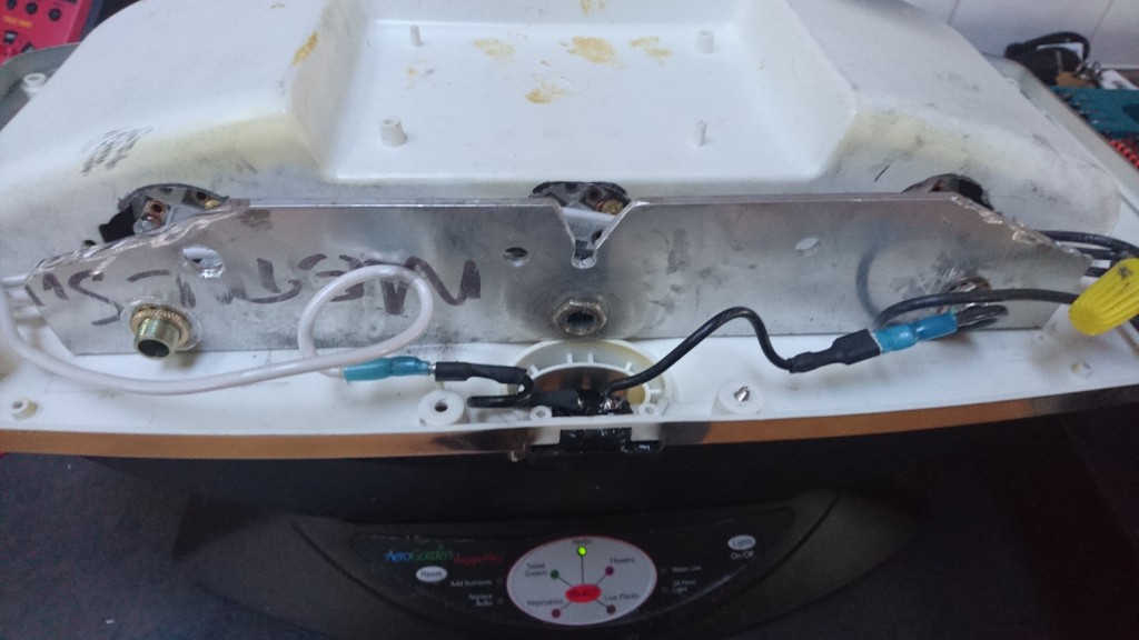
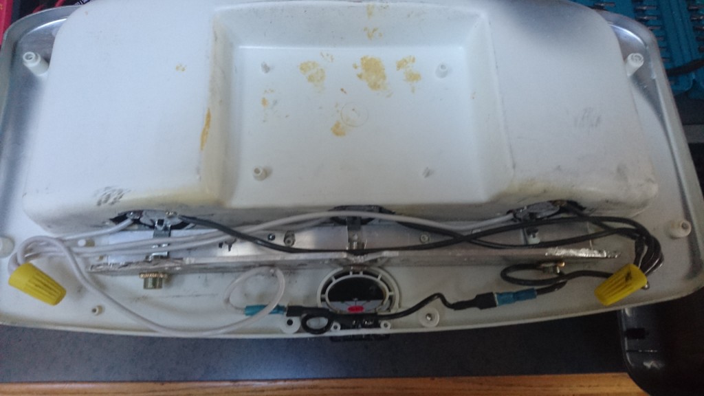
I didn’t take pictures along the way but the hack is pretty simple.

  1. Disassemble the light fixture – 2 of the bolts are Torx. You don’t need to remove the 2 screws next to the power plug
  2. Remove the old power supply and CFL mounting brackets
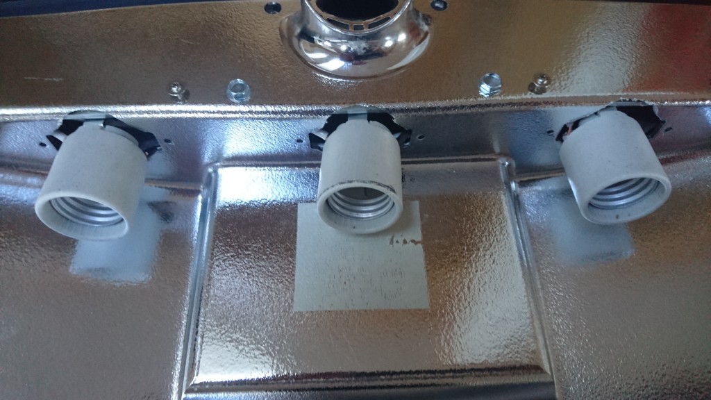
  3. Mark the size of the holes for the new light fixtures – medium socket
  4. Cut out the holes with a Dremel. I left the original CFL mounting holes in case I wanted to go back to the old bulbs.
  5. Cut a piece of aluminium L bracket to length and height. Notice there is a notch part way though the light fixture that you need to make room for. I also added 4 holes for alignment to the old screw mounts. I would check to make sure that the fixture has room to close properly at this point.
  6. Attach some 14 gauge wire to the bases and mount them to the L bracket.
  7. Attach the new wire to the power plug on the fixture.
  8. Slide the bases through the holes from step 3.
  9. Mount the L bracket to the fixture with 2 Tek self taping bolts.
  10. Re-assemble the fixture and you’re all done.

DSC_0214

DSC_0215
DSC_0213

I’ve currently got 3 60W incandescent grow bulbs in there but I’m on the lookout for some LED or CFL grow lights.

SWD with the MDBT40 BLE module

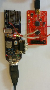
IMG_20150301_173929

I was recently introduced to the MDBT40 module that is based on the Nordic nRF51822. The processor nicely solves a number problems I’ve been looking at and the fact that it’s Bluetooth Smart also solves how I’ll get the data from it.

I designed some custom hardware ( the picture at left ) around the module and I needed some way to program it. My earlier post shows my investigations with SWD and OpenOCD.I put a SWD header on the board to re-program it.

OpenOCD Configuration for the nRF51822

bishop on the Nordic Developer Zone figured out how to get the nRF51822 part working with S-Link and OpenOCD. I took his configuration and adjusted it to work with the bus blaster v3.

source [find  interface/ftdi/dp_busblaster_kt-link.cfg]
transport select swd
set WORKAREASIZE 0
source [find target/nrf51.cfg]

Save it as nrf51822.cfg so then you can start openocd with it.

$ openocd -f target/nrf51822.cfg

OpenOCD defaults to a telnet interace on 4444.

$ telnet 127.0.0.1 4444
Trying 127.0.0.1...
Connected to 127.0.0.1.
Escape character is '^]'.
Open On-Chip Debugger
> halt                                    
target state: halted
target halted due to debug-request, current mode: Thread
xPSR: 0x21000000 pc: 0x000163da msp: 0x20003fd8
> nrf51 mass_erase                        
> flash write_image _build/akkea1_tfw.hex
Padding image section 0 with 2112 bytes
Padding image section 1 with 3572 bytes
Padding image section 2 with 1 bytes
not enough working area available(requested 32)
no working area available, falling back to slow memory writes
wrote 95556 bytes from file _build/akkea1_tfw.hex in 14.267832s (6.540 KiB/s)
> reset

The board is now prgrammed with your custom firmware. This should work with any MDBT40 based board the has the 12K programming resistor per the Raytac application note. It should also work with other nRF51822 based board with a SWD interface

Recovering a bricked CC3D board using a bus blaster

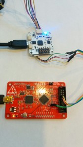
IMG_20150214_155435A few months ago I went to upgrade my OpenPilot CC3D board an something went amiss and I ended up trashing the bootloader. I didn’t have a SWD dongle to reprogram it with so its been collecting dust. I just purchased a v3 bus blaster for a different project I’m working on and it has a SWD firmware so I thought I’d try and recover the CC3D. Below are the steps I used.

Download and install the latest OpenOCD

git clone git://git.code.sf.net/p/openocd/code openocd
cd openocd/
./bootstrap
./configure --prefix=/usr
make
sudo make install

Re-flash the Bus Blaster v3 for KT-link buffer

The instructions below came from here

git clone https://github.com/bharrisau/busblaster.git
cd busblaster/synthesis
openocd -f board/dp_busblaster_v3.cfg -c "adapter_khz 1000; init; svf system.svf; shutdown"

Getting/Building the bootloader

Now you need to get a bootloader to flash into the CC3D. You might be able to download bl_coptercontrol.hex but I’ve already got the OpenPilot development environment installed so I just built it using

make all_bl all_bu

If you don’t have the dev environment setup there are build instructions.

Here is the file I used bl_coptercontrol.hex but the regular disclaimers apply, if this file damages or bricks your CC3D I am not responsible.

OpenOCD config file

You need create a flashing script “cc3d-swd.cfg” to pass to OpenOCD.

source /usr/share/openocd/scripts/interface/ftdi/dp_busblaster_kt-link.cfg
transport select swd
source [find target/stm32f1x.cfg]

proc program_device () {
    reset init
        sleep 50
        flash probe 0
        sleep 50
        flash protect 0 0 last off
        sleep 50
        flash write_image erase unlock "path_to_hex_file/bl_coptercontrol.hex"
        sleep 50
        reset run
}

init
program_device ()
exit

Obiously replace “path_to_hex_file” to where you built or downloaded bl_coptercontrol.hex

Connect the bus blaster to the CC3d

I got the cable connections from here.

     adapter         ┊            target
                     ┊
     GND ──────────────────────── GND
                     ┊
     TCK ──────────────────────── SWCK
                     ┊
     TMS ──────────────────────── SWDAT
                     ┊

Finally reflashing the CC3D bootloader

openocd -f cc3d-swd.cfg

Mini Quadcopter Parts

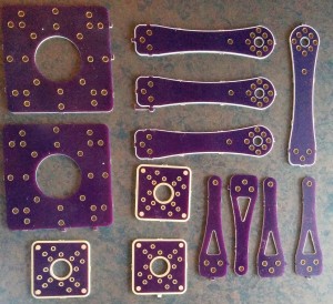
I created some CAD drawings for quadcopter parts I kept breaking. I got tired of making and cutting out the fibreglass myself so I created some Oshpark boards.

You can go here to order your very own Quadcopter parts

Here’s what the first batch looked like. I didn’t like the look of the power board so I did a new layout for my second batch.

I’ve tried the screw positions with the KK multirotor board and the CC3D flight control board.

IMG_20150116_164459

AP510 APRS

I recently got my amateur radio certificate and was interested doing some APRS messaging so I purchased a Sainsonic AP510. It’s a nice little TNC with GPS, bluetooth and a thermometer.

It comes with minimal documentation in 4 languages and no software to configure it.

There’s a Yahoo Group that has firmware, configuration software and upgrade software. It’s annoying that you need to sign up for a Yahoo account to download the files there.

There’s also a Chinese website that has more firmware and some forums ( the Yahoo site has mined most needed data from there )

There’s also a good French website that explains how to flash the firmware and has some files needed for windows 7.

I found a German site that explains the serial cable pinout.

Upgrading the firmware

Standard disclaimer: this has worked for me but if it fails and bricks your AP510 I’m not responsible.

So far I have only gotten this to work on Windows, it will run under Wine but won’t connect. On windows XP these files AVRTTupdata.exe.zip and the VB6 runtime will be enough. On any newer windows MSCOMM32.OCX and MSSTDFMT.DLL will be required as well.

Make sure the ini file is in the same directory as the AVRTTupdata when you run it as it has the correct setup for the AVR in the AP510. The first time you run AVRTTUpdata it will be in Chinese, select language and put it into English.

  1. Use the option->comport menu item to chose the correct comport. Don’t change any of the other settings.
  2. Use the folder icon to load the hex file into the Upgrade tool.
  3. Turn off the AP510.
  4. Push and hold the power button on the AP510.
  5. While still holding the power button push the chip icon and the download will begin.
  6. Keep holding the power button until the download completes.

Voila your AP510 is now upgraded.

Linux Configuration tool

Update: This is deprecated use chirp instead as it now supports the AP510

The windows configuration tool is in the archive above. I didn’t want to start up a VM each time to change the config so I wrote a simple python tool AP510-setup to configure it. You’ll need to edit the script to change the comport, callsign and other settings. I’ve licensed it GPL V2 and please send me any improvements you make to the script.

To use the script:

  1. Edit the configuration
  2. Turn the AP510 off
  3. Start the script
  4. Turn the AP510 back on
  5. The script should dump the current settings, update the new settings and then dump the new settings

EDIT: Jan was nice enough to reverse engineer a schematic for the AP510.

Hobby King X230 replacement parts

I purchased the X230 Quad copter kit from hobby king in December. I’ve been learning to fly it and in the process have been breaking parts.

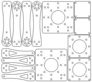
Hobby king doesn’t sell replacement parts so I’ve been patching it up as I go along. Some of the pieces are getting too broken to be patched. I’ve created a DXF of the parts and I’m going to have them built out of carbon fibre for increased crash resistance 🙂

Quad_designAt left is a 1:2 jpeg of the parts. If you’d like the DXF it’s here

If you’d like the SVG it’s here

Edit: I don’t recommend using carbon fibre to prototype this unless you have a laser cutter.

i’m Watch Accelerometer

I tried to get the part number for the accelerometer from im Watch developer support and they refused to give it to me. The response was you don’t need need that information just use the supplied sensor library. I tried to tell them the library would only collect data at 10 Hz and I require 200 Hz. It also wastes time by always sampling the magnetometer and the accelerometer even if you only need the accelerometer data.

After trying for a few days to get the information from developer support I decided to figure it out for myself.

I wrote a little i2c scanner and enumerated the devices on the bus. I found a device at 0x19 and 0x1e. now to figure out what they are. I disassembled the the sensor library supplied by imdeveleoper.it and found the hex constant 0x19 in the initAccel function. So far so good.

I then stepped up my scanner to read all of the registers from 0 to 127. The first register was at 0x7 and the second was at 0xF and then a bunch more upto 0x2F. I had expected some kind of who am I at 0x0. No such luck. I re-read the registers a few times looking for the changing values. The values at 0x28 to 0x2d changed with the orientation of the device. Good I’ve found the accelerator, but which one ?

I started going through accelerometer datasheets and found that the st micro parts had a who_am_i variable at 0xF. I finally found a match, 0x33 in the LIS3DSH datasheet. The changing values also correspond to the locations of the x, y and z values  so I’m pretty sure I’ve found the correct part. EDIT: i’m Watch support finally got back to me and it is actually the LSM303DLHC. The magnetometer and thermometer are both integrated.

So now I get to re-write the imWatch sensor library. The good news is that the accelerometer has a FIFO, can sample at 5KHz and has a temperature sensor. After I’ve re-written the sensor lib I’m going to see what’s hiding in the magnetometer.


i’m Watch Sensors

After almost a year the IMWatch developer site has finally released a library to access the sensors. They even released an example application but no documentation ???

Fortunately there are some tools to decompile java apps.

Below are the prototypes for the two undocumented functions the you’ll need to use to get access to the sensors.

public SensorServiceInstance(int updateInterval)
public SimpleShakeDetector(Context context, OnShakeListener listener, int updateInterval)

The important argument here is the updateInterval. It’s an int but what does it represent. A few tests show it’s the number of milliseconds between samples. Reading the decompiled code implies that this value must be greater than zero but has no other limits.

The application I’m writing needs to have a 200Hz update rate so I tried setting this value to 5 ms. This doesn’t get the required update rate. It seems the practical lower limit to updateInterval is 100ms which doesn’t even match the game update interval for the Android standard sensors updates. 10 Hz isn’t even the lowest rate I can use for my application.

Digging deeper into the sources looks like they have included a native i2c library to access the sensors. I might be able to use that to get direct access and increase the update rate. Stay posted for a blog post on where I get with that.

The full decompile source is available here.

Once again IMWatch has underwhelmed with no documentation and a marginally functional sensor library.  Another release, another fail.