I found a new way to scale STLs in FreeCAD where you don’t need to use the Python console.
Import the STL.
Go to the Part Workbench.
Select the STL in the Model list
Menu: Part->Create shape from mesh…
Select the new part
Menu: Part->convert to solid
Select the new part
Menu: Part->Refine shape
Change to the Draft Workbench
Menu: Draft->Clone
Now you can adjust the scale in the properties window of the clone.
Upverter has a nice STL export ( when it works ) of your board so you can do mechanical modelling for your design. Unfortunately when it gets imported into FreeCAD the scale is 10 times too small.
FreeCAD as of 0.15 does not have menu item that allows you to scale mesh imports. Luckily the python console can do the scaling of imported meshes.
First import the mesh ( STL file ) that you want to add to the current design. Select it in the “Combo view->Model” tree on the left of the FreeCAD screen. Then use the python console ( View->Views->Python console ) with the code below to scale it up 10 times.
I’ve had this Aerogarden for a while but most of it’s life has been spent in a box in the garage because the lights quit working shortly after the 1 year warranty ran out. I decided to take it out this weekend and figure out what the issue was.
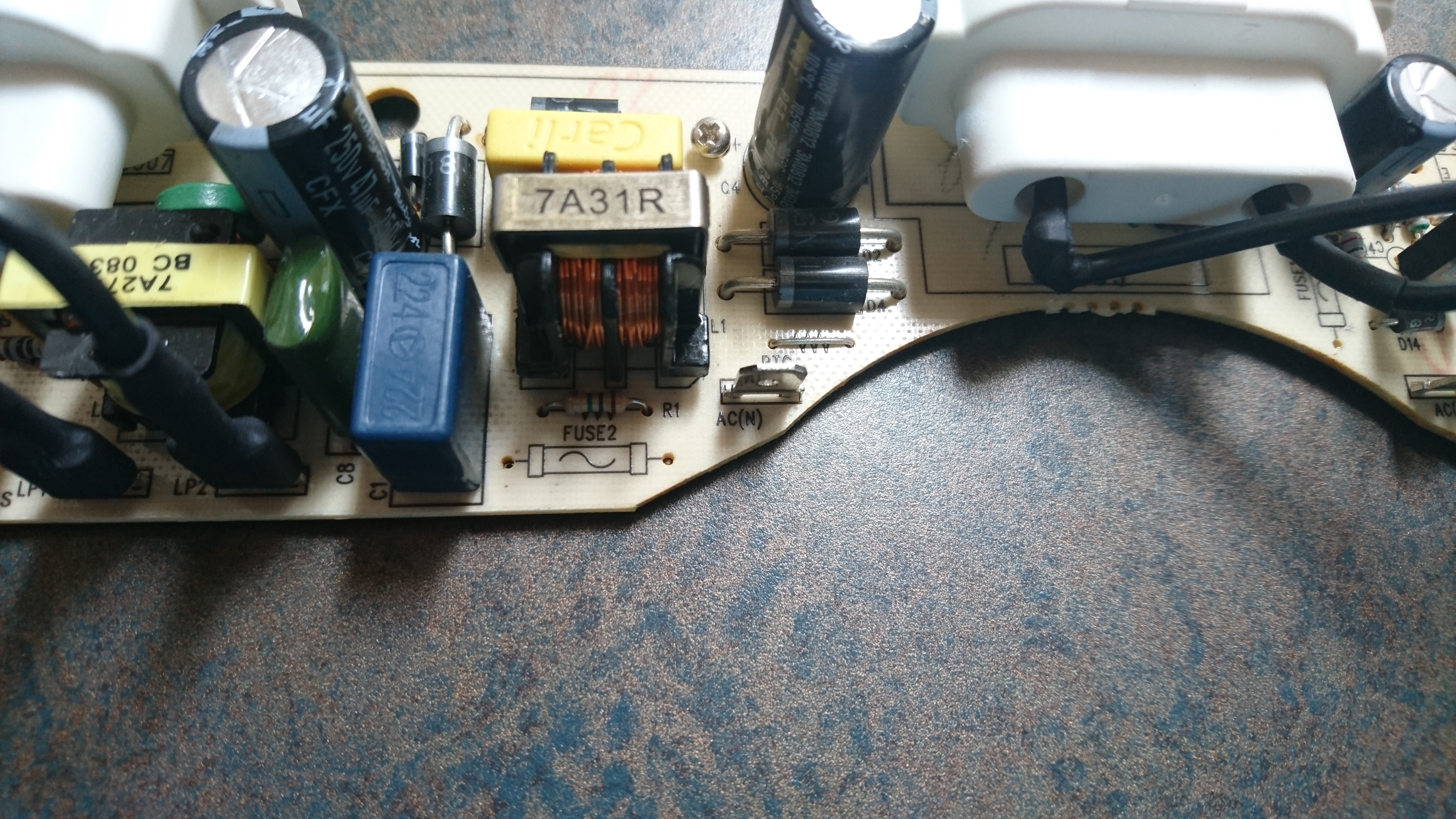
I disassembled the the light fixture and pulled out the power board and there are 2 250V 3A fuses on there. Both of then were blown. I de-soldered those thinking I would just replace them and the board would work. Then I got to thinking why do I want to fix the power supply for the proprietary ( and not very long lasting ) bulbs so instead I hacked it to take A19 ( “standard” ) light bulbs.
I didn’t take pictures along the way but the hack is pretty simple.
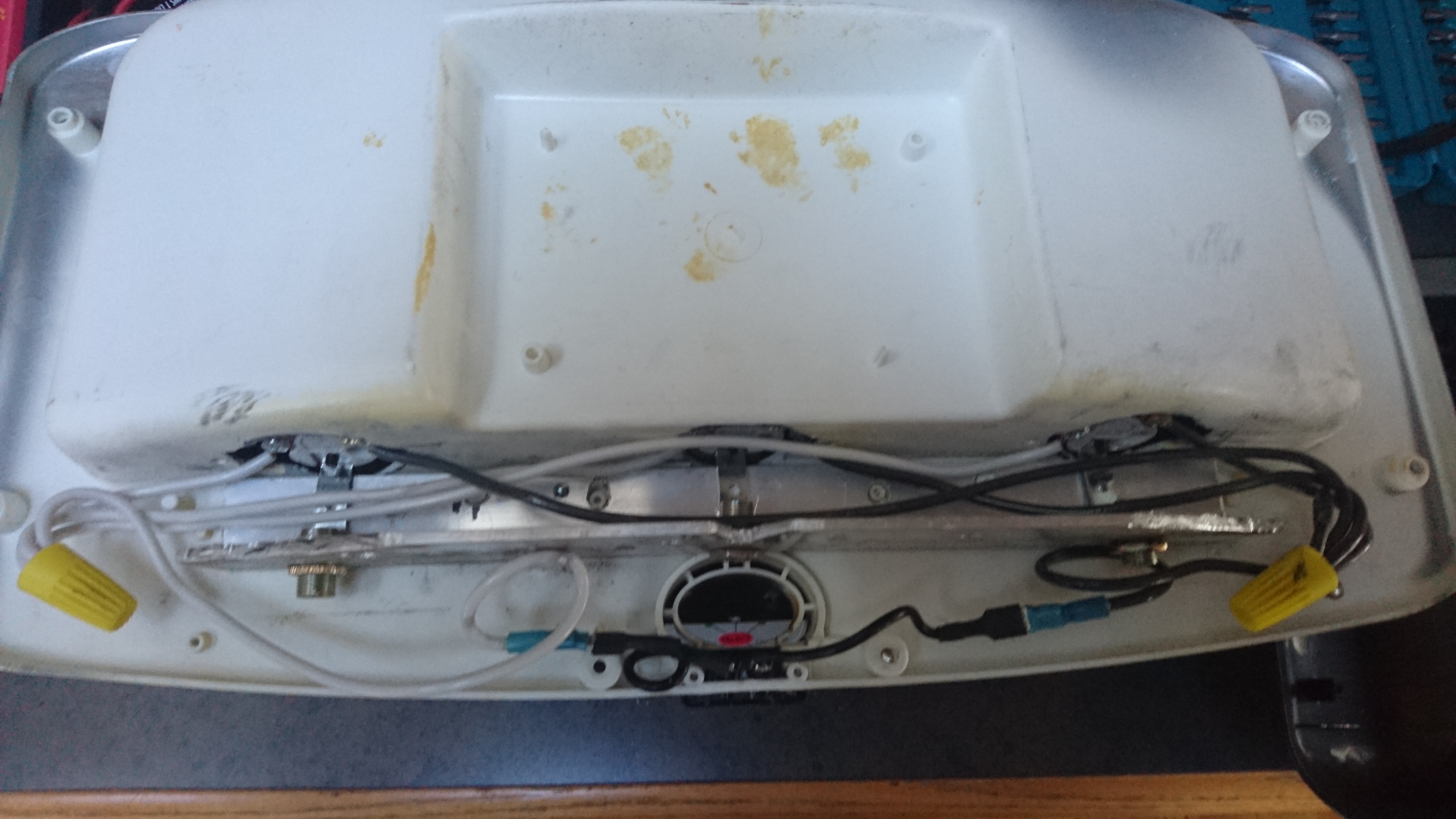
Disassemble the light fixture – 2 of the bolts are Torx. You don’t need to remove the 2 screws next to the power plug
Remove the old power supply and CFL mounting brackets
Mark the size of the holes for the new light fixtures – medium socket
Cut out the holes with a Dremel. I left the original CFL mounting holes in case I wanted to go back to the old bulbs.
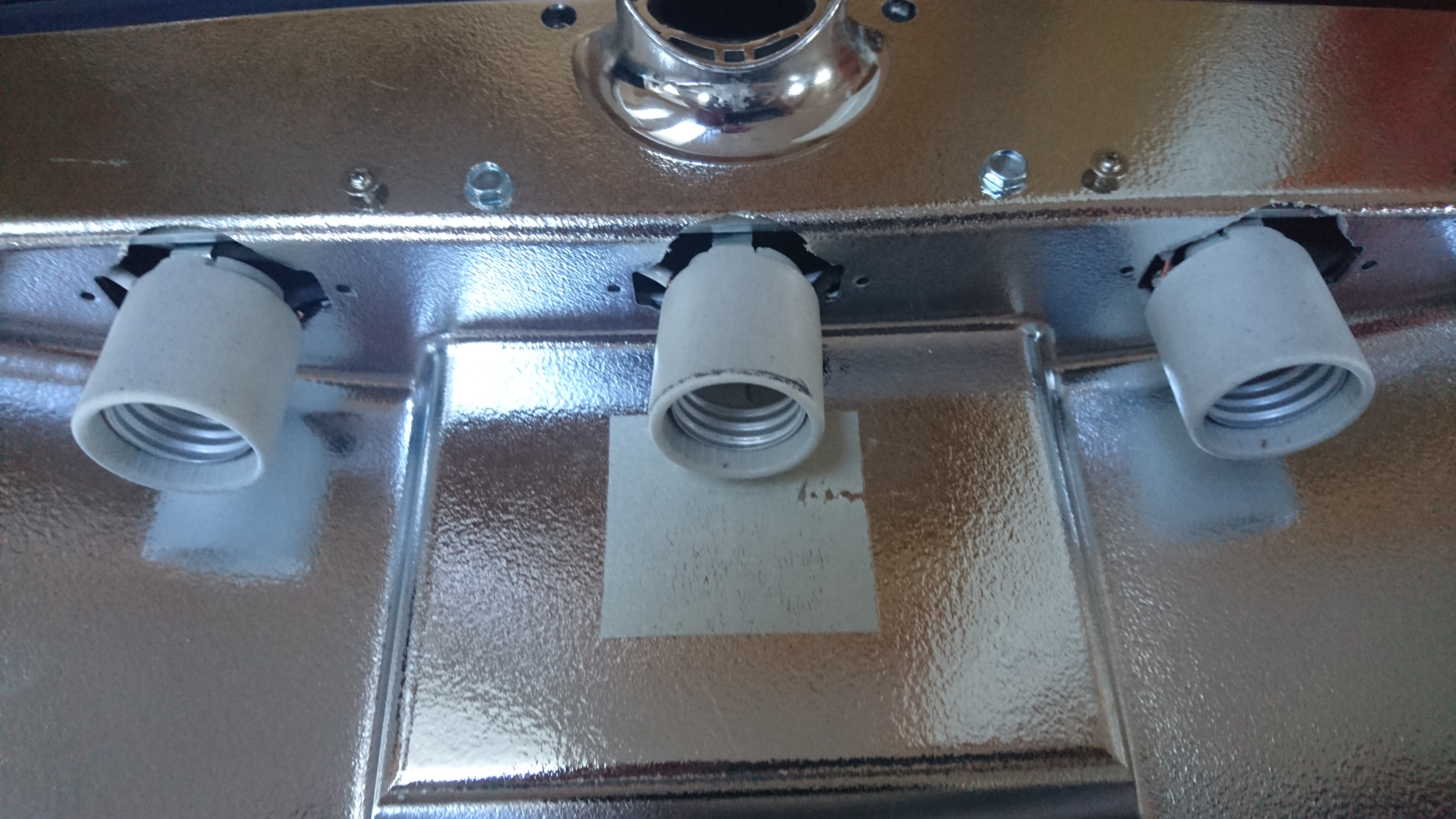
Cut a piece of aluminium L bracket to length and height. Notice there is a notch part way though the light fixture that you need to make room for. I also added 4 holes for alignment to the old screw mounts. I would check to make sure that the fixture has room to close properly at this point.
Attach some 14 gauge wire to the bases and mount them to the L bracket.
Attach the new wire to the power plug on the fixture.
Slide the bases through the holes from step 3.
Mount the L bracket to the fixture with 2 Tek self taping bolts.
Re-assemble the fixture and you’re all done.
I’ve currently got 3 60W incandescent grow bulbs in there but I’m on the lookout for some LED or CFL grow lights.
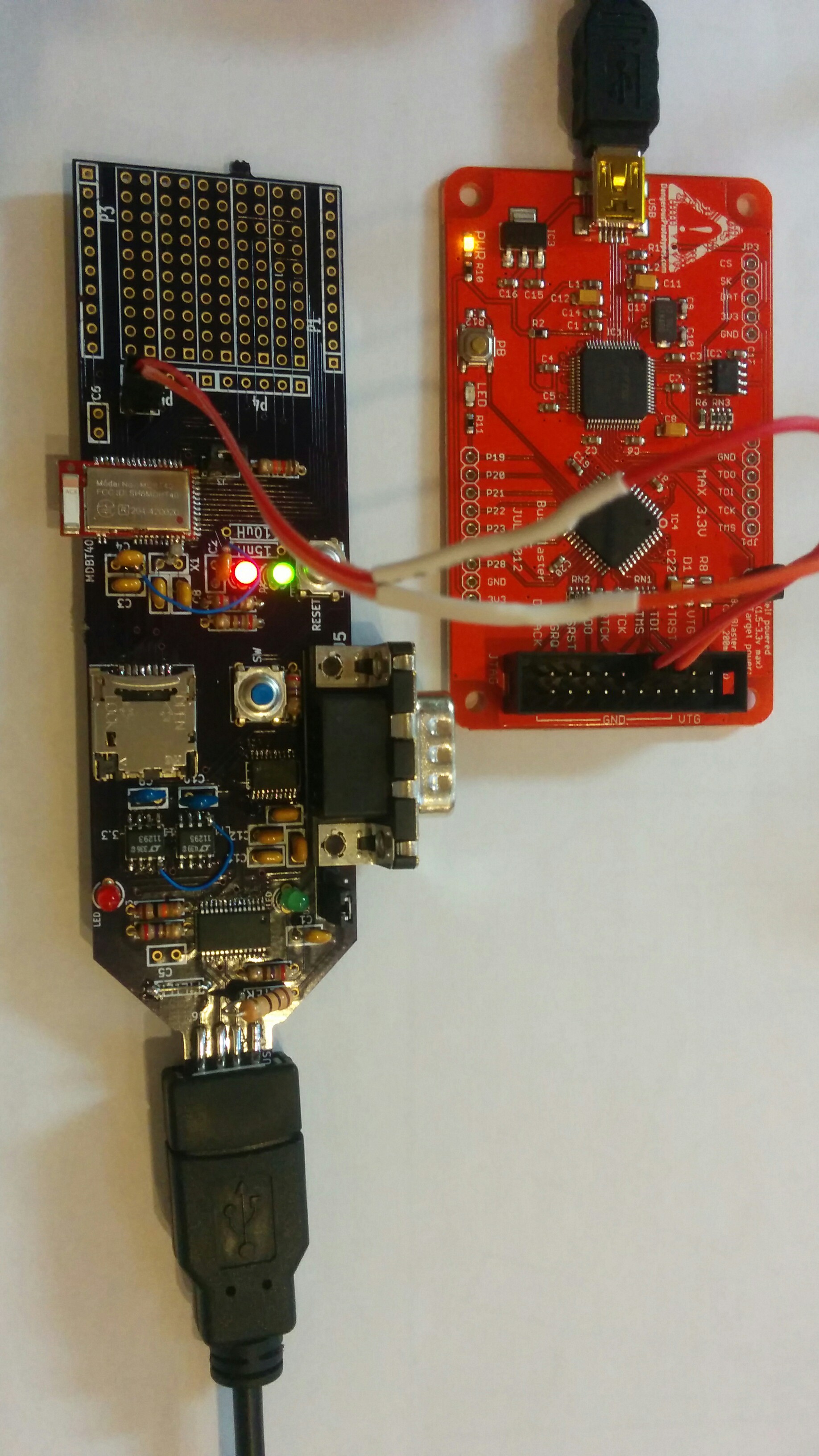
I was recently introduced to the MDBT40 module that is based on the Nordic nRF51822. The processor nicely solves a number problems I’ve been looking at and the fact that it’s Bluetooth Smart also solves how I’ll get the data from it.
I designed some custom hardware ( the picture at left ) around the module and I needed some way to program it. My earlier post shows my investigations with SWD and OpenOCD.I put a SWD header on the board to re-program it.
OpenOCD Configuration for the nRF51822
bishop on the Nordic Developer Zone figured out how to get the nRF51822 part working with S-Link and OpenOCD. I took his configuration and adjusted it to work with the bus blaster v3.
source [find interface/ftdi/dp_busblaster_kt-link.cfg]
transport select swd
set WORKAREASIZE 0
source [find target/nrf51.cfg]
Save it as nrf51822.cfg so then you can start openocd with it.
$ openocd -f target/nrf51822.cfg
OpenOCD defaults to a telnet interace on 4444.
$ telnet 127.0.0.1 4444
Trying 127.0.0.1...
Connected to 127.0.0.1.
Escape character is '^]'.
Open On-Chip Debugger
> halt
target state: halted
target halted due to debug-request, current mode: Thread
xPSR: 0x21000000 pc: 0x000163da msp: 0x20003fd8
> nrf51 mass_erase
> flash write_image _build/akkea1_tfw.hex
Padding image section 0 with 2112 bytes
Padding image section 1 with 3572 bytes
Padding image section 2 with 1 bytes
not enough working area available(requested 32)
no working area available, falling back to slow memory writes
wrote 95556 bytes from file _build/akkea1_tfw.hex in 14.267832s (6.540 KiB/s)
> reset
The board is now prgrammed with your custom firmware. This should work with any MDBT40 based board the has the 12K programming resistor per the Raytac application note. It should also work with other nRF51822 based board with a SWD interface
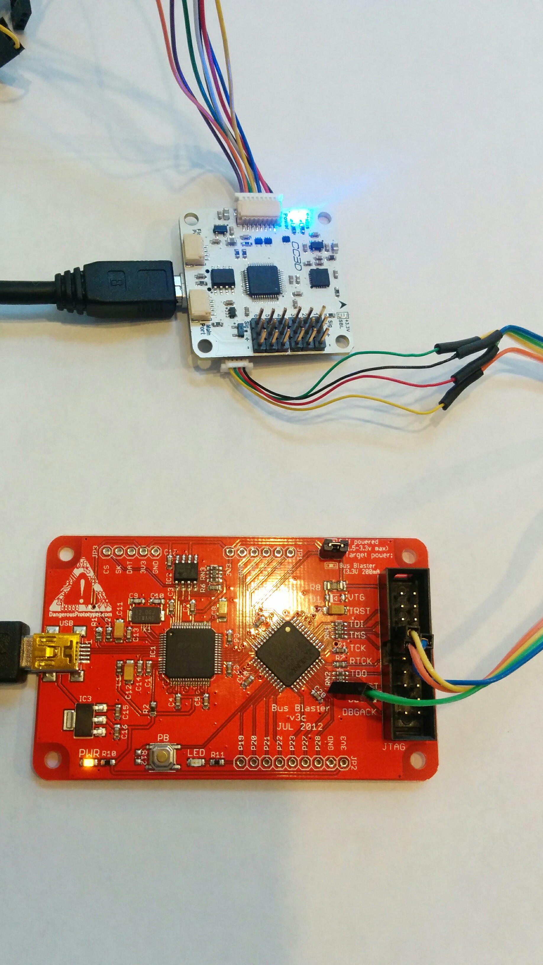
A few months ago I went to upgrade my OpenPilot CC3D board an something went amiss and I ended up trashing the bootloader. I didn’t have a SWD dongle to reprogram it with so its been collecting dust. I just purchased a v3 bus blaster for a different project I’m working on and it has a SWD firmware so I thought I’d try and recover the CC3D. Below are the steps I used.
Download and install the latest OpenOCD
git clone git://git.code.sf.net/p/openocd/code openocd
cd openocd/
./bootstrap
./configure --prefix=/usr
make
sudo make install
Now you need to get a bootloader to flash into the CC3D. You might be able to download bl_coptercontrol.hex but I’ve already got the OpenPilot development environment installed so I just built it using
make all_bl all_bu
If you don’t have the dev environment setup there are build instructions.
Here is the file I used bl_coptercontrol.hex but the regular disclaimers apply, if this file damages or bricks your CC3D I am not responsible.
OpenOCD config file
You need create a flashing script “cc3d-swd.cfg” to pass to OpenOCD.
source /usr/share/openocd/scripts/interface/ftdi/dp_busblaster_kt-link.cfg
transport select swd
source [find target/stm32f1x.cfg]
I created some CAD drawings for quadcopter parts I kept breaking. I got tired of making and cutting out the fibreglass myself so I created some Oshpark boards.
I recently got my amateur radio certificate and was interested doing some APRS messaging so I purchased a Sainsonic AP510. It’s a nice little TNC with GPS, bluetooth and a thermometer.
It comes with minimal documentation in 4 languages and no software to configure it.
There’s a Yahoo Group that has firmware, configuration software and upgrade software. It’s annoying that you need to sign up for a Yahoo account to download the files there.
There’s also a Chinese website that has more firmware and some forums ( the Yahoo site has mined most needed data from there )
There’s also a good French website that explains how to flash the firmware and has some files needed for windows 7.
I found a German site that explains the serial cable pinout.
Upgrading the firmware
Standard disclaimer: this has worked for me but if it fails and bricks your AP510 I’m not responsible.
So far I have only gotten this to work on Windows, it will run under Wine but won’t connect. On windows XP these files AVRTTupdata.exe.zip and the VB6 runtime will be enough. On any newer windows MSCOMM32.OCX and MSSTDFMT.DLL will be required as well.
Make sure the ini file is in the same directory as the AVRTTupdata when you run it as it has the correct setup for the AVR in the AP510. The first time you run AVRTTUpdata it will be in Chinese, select language and put it into English.
Use the option->comport menu item to chose the correct comport. Don’t change any of the other settings.
Use the folder icon to load the hex file into the Upgrade tool.
Turn off the AP510.
Push and hold the power button on the AP510.
While still holding the power button push the chip icon and the download will begin.
Keep holding the power button until the download completes.
Voila your AP510 is now upgraded.
Linux Configuration tool
Update: This is deprecated use chirp instead as it now supports the AP510
The windows configuration tool is in the archive above. I didn’t want to start up a VM each time to change the config so I wrote a simple python tool AP510-setup to configure it. You’ll need to edit the script to change the comport, callsign and other settings. I’ve licensed it GPL V2 and please send me any improvements you make to the script.
To use the script:
Edit the configuration
Turn the AP510 off
Start the script
Turn the AP510 back on
The script should dump the current settings, update the new settings and then dump the new settings
EDIT: Jan was nice enough to reverse engineer a schematic for the AP510.
I figured out how to read and write the i2c bus on the imWatch so I can now sample at whatever rate I’d like. This tarball includes code that should work upto 200Hz without overloading the processor.
Faster rates should be possible but it would mean getting the FIFO in the accelerometer working and then backdating the samples.
Building the JNI
I’m not going to detail how to use a JNI within an Android project. there are plenty of other tutorials out there.
From the tarball put “akkea-jni.c” and “Android.mk” into the jni directory of your android >project. Then run
Add these native prototypes and constants to your android code.
public native int readAccel( SeismoVector vector, int fd, long startTime );
public native int openI2c( String path );
public native void closeI2c( int fileHandle );
public native int i2cReadReg( int file, int addr, int reg);
public native int i2cWriteReg( int file, int addr, int reg, int val);

int i2cHandle;
final byte ACCEL_I2C_ADDR = 25;
final int ACCEL_RATE_OFF = 0;
final int ACCEL_RATE_1HZ = 1 << 4;
final int ACCEL_RATE_10HZ = 2 << 4;
final int ACCEL_RATE_25HZ = 3 << 4;
final int ACCEL_RATE_50HZ = 4 << 4;
final int ACCEL_RATE_100HZ = 5 << 4;
final int ACCEL_RATE_200HZ = 6 << 4;
final int ACCEL_RATE_400HZ = 7 << 4;
final int ACCEL_RATE_1_6KHZ = 8 << 4;
final int ACCEL_RATE_5KHZ = 9 << 4;
The I2C bus and accelerometer need to be setup
public boolean openI2C() {

  try
  {
    Runtime.getRuntime().exec("chmod 777 /dev/i2c-0");
  } catch (IOException e) {
    e.printStackTrace();
  }

  i2cHandle = openI2c( "/dev/i2c-0" );

  if( i2cHandle <= 0 )
    return false;

  int[] arr = new int[4];
  for( int i=0; i<128; i++ ) {
    arr[0] = i2cReadReg( i2cHandle, ACCEL_I2C_ADDR, i );
    if( arr[0] != 0 )
      Log.d(TAG, "Register " + String.valueOf( i ) + " = " + String.valueOf( arr[0] ));
  }

  int val;
  val = i2cReadReg( i2cHandle, ACCEL_I2C_ADDR, 0x20 );
  val = ( val & 0x0F );

  switch( HZ ) {
    case 1:
      val |= ACCEL_RATE_1HZ;
      break;
    case 10:
      val |= ACCEL_RATE_10HZ;
      break;
    case 25:
      val |= ACCEL_RATE_25HZ;
      break;
    case 100:
      val |= ACCEL_RATE_100HZ;
      break;
    case 200:
      val |= ACCEL_RATE_200HZ;
      break;
    case 400:
      val |= ACCEL_RATE_400HZ;
      break;
    case 1600:
      val |= ACCEL_RATE_1_6KHZ;
      break;
  }

  i2cWriteReg( i2cHandle, ACCEL_I2C_ADDR, 0x20, val );

  val = i2cReadReg( i2cHandle, ACCEL_I2C_ADDR, 0x20 );
  Log.d(TAG, "Register Rate " + String.valueOf( val ));

  return true;
}
I then use a TimerTask to read the accelerometer at whatever rate I want.
class sensorTask extends TimerTask {
  @Override
    public void run() {
      long time;

      if( index >= totalSamples ) {
        Log.d(TAG, "index past end of array");
        return;
      }

      SeismoVector vector = new SeismoVector();

      time = readAccel( vector, i2cHandle, startTime );

      if( startTime == 0 )
        startTime = time;

      vectors[index++] = vector;

    }
};
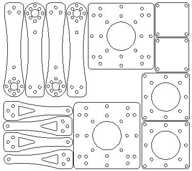
I purchased the X230 Quad copter kit from hobby king in December. I’ve been learning to fly it and in the process have been breaking parts.
Hobby king doesn’t sell replacement parts so I’ve been patching it up as I go along. Some of the pieces are getting too broken to be patched. I’ve created a DXF of the parts and I’m going to have them built out of carbon fibre for increased crash resistance 🙂
At left is a 1:2 jpeg of the parts. If you’d like the DXF it’s here
About a year ago I was contacted to write some iOS software to measure tremor in MS patients. I have no interest in writing iOS software. The only real hardware requirement was that the device had an accelerometer so I suggested using an Android device instead. The device would need to be fastened to the patients arm and be lightweight to limit it’s influence on the tremor. The perfect fit seemed to be an Android watch.
There were two capable Android watches available at the time, the WiMM One module and the i’m Watch. The WiMM One was already shipping, had stock and a price point less than half of what the I’m Watch was going for. At the time the i’m Watch was taking pre-orders with a promise of shipping soon.
I ordered a few of he WiMM modules and got to work writing the beta software on a Nexus S. I demoed the first version two weeks later.
The Software
Once the demo proved that I could get the desired sample rates I started shrinking it down and learning the WiMM API. Most of the differences lie in the way that the application screens are laid out. That allowed me to keep most of the functional code from the demo application.
The application is very simplistic from a GUI perspective in that it only displays a single button and a countdown timer. This is partly because the application needs limited user feedback but it’s also due to potential users of the application. One of the uses would be to monitor outpatients to track their tremor over time without requiring a clinic visit. These users would have limited eye hand coordination so the simpler the interface the better.
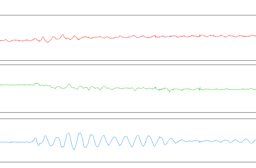
Another reason for targeting the WiMM device was it included wifi that would allow automated data collection. After collecting a data series the watch would connect to a server to upload the data. Once uploaded the data would be saved as a CSV. Then GNUplot was used to transform the CSV into a line graph of the X, Y and Z axes. After the data gets plotted the server also does an FFT and plots that. The FFT is done to expose any frequency elements in the tremors.
This is an example of the post processed data
Challenges
There were a number of challenges with using the WiMM watch. I was familiar with Android 1.6 but the version on the WiMM is slightly modified for the smaller screen and other hardware peculiarities.
On of the challenging differences is the watch doesn’t follow the Android sensor API for the accelerometers. You are able to set a rate using the defines SENSOR_DELAY_FASTEST, SENSOR_DELAY_GAME and SENSOR_DELAY_NORMAL however you can’t specify an absolute rate for updates. To get around this issue I sampled at the highest rate possible ( 200Hz ) and decimated the samples I didn’t need.
Using this technique I was able to get 100, 150 and 200Hz sample rates. For the most part this did work well but rates over 100Hz still had problems. There were occasional gaps in the data that lasted upto 120ms. After some investigation I found the Dalvik GC was logging with times that were amazingly close to some of the gaps in my data.
By pre-allocating as many of the accelerometer data structures as possible I reduced the number of garbage collection cycles and the subsequent spaces in the data. Even once I solved this there are still the occasional gaps. My best guess at this point is that the accelerometer and the GUI are running at the same priority and occasionally collide.
Successes
The table at left shows a comparison between the WiMM module and a Entran accelerometer. The WiMM is sampling at 100Hz and the Entran around 2KHz. The data shows that the WiMM compares quite well to the standard analog sensor.
Tremors in people are well below the 50Hz that the WiMM should be able to resolve so it would function as an acceptable measurement device for in or out-patients with temors and tremor related diseases.
Data is starting to come in from the studies using the software. It is showing some interesting repetitive osculations which we expected. At right is an excerpt from a MS patient recorded during a clinic visit.
There are currently 2 studies using the software, below is a synopsis of their work. Both of them should be publishing some of the results soon.
Study #1
Traditional tools for accelerometry are cumbersome and do not lend themselves to routine clinical use. Using a smart watch device for accelerometry makes data collection very simple and portable, and may allow for wider use of accelerometry for tremor analysis. The potential of the on-board hardware for data processing and display makes this even more exciting. As a proof of concept, I am collecting accelerometer data simultaneously from the WIMM One and a standard analog accelerometer, and coanalyzing the data offline in the MATLAB environment to determine whether the performance of the WIMM One is acceptable. After this, I am collecting data from patients with Parkinson disease and Essential tremor to compare some aspects of these tremors to see if the portable device might be a useful diagnostic tool.
Daryl Wile, MD, MSc
Neurology Resident
University of Calgary
Study #2
As a clinician-scientist, I envision both clinical and research-oriented applications for watch-based accelerometry in the evaluation of tremor in Multiple Sclerosis (MS).
Clinically, I frequently encounter tremor in MS (MST). It is notoriously difficult to treat, meaning that patients need to try many interventions before (if ever) we find one that works. This problem is compounded by: (1) patient mobility and transportation issues – it is difficult and inconvenient for patients to return to the clinic frequently for re-evaluation of treatment efficacy, and (2) clinic availability – usually, I can only follow-up with patients every six months.
In research trials, it is necessary to have patients return frequently to the clinic for re-evaluation (which is problematic), and it is ideal to have a simple technique for quantifying tremor response to treatment.
By collecting tremor data remotely, treatment efficacy can be evaluated quickly, quantitatively, and conveniently. In clinical terms, this means we waste little time finding a treatment that works. In research terms, this allows us to objectively evaluate, with minimal inconvenience to the patient, potential new therapies for treating MST.
Scott E Jarvis MD PhD FRCPC (Neurology)
MS Clinical Fellow
University of Calgary
Future Directions
WiMM has gone dark about what their future holds and has stopped selling the devices. They have also dropped all developer support.
This is where the i’m Watch comes into play. I’ve managed to reverse engineer the accelerometer and magnetometer in the watch and I’m currently rewriting the application to work on the new device. I’ve already written a native i2c library that can get data from the watch and it is sampling at 100Hz.
Next I’ll need to establish the accuracy of the new accelerometer so it can be used to replace the WiMM watch.
Wishlist for future releases
I’d like do some of the frequency analysis done directly on the watch.
Plotting would be nice too but I suspect viewing it on the small screen would be cumbersome.
The new accelerometer has a FIFO so I might be able to get reliable data at a faster rate than I can get timer ticks.
Use the form below if you’d like to contact me or either of the Doctors running the studies.


